Home/Capabilities

Automation-led aluminium die casting, engineered for volume and safety-critical tolerance.

Gravity die casting is our single, deep discipline, refined over a decade on safety-critical brake components. Four stages, three alloys, one accountable team.

SectionProcess

Melt → Cast → Heat treat → Inspect.

Tower-type melting
01 · Melt
Tower-type melting

Six tower furnaces, verified chemistry every melt.

A continuous melt of AC2A, LM16 or Al-Si7 is held to spec and verified by optical-emission spectrometer before any metal enters a die. Holding-bath temperature is PLC-controlled and logged against the part-specific recipe.

  • Furnaces6 × tower
  • AlloysAC2A · LM16 · Al-Si7
  • Pour temp680 – 740 °C
  • Chemistry QCOE spectrometer
Gravity die casting
02 · Cast
Gravity die casting

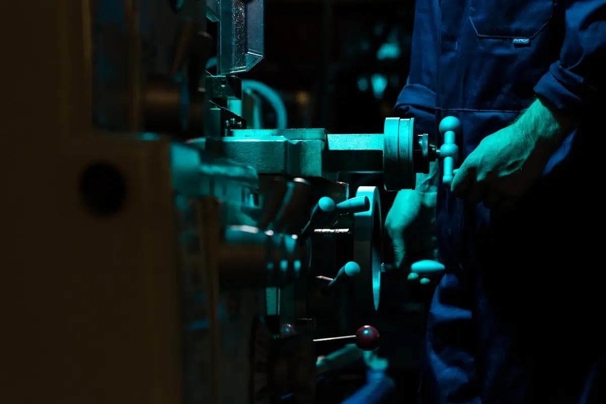
44 GDC machines with auto-pour and PLC cycle control.

Cycle time, pour profile and die-temperature traces are logged for every shot, giving us the process-capability data Tier-1 customers need at PPAP and through volume production. Part-weight range 100 g to 1.5 kg.

  • Machines44
  • Auto-pourStandard
  • Part range100 g – 1.5 kg
  • TraceabilityPLC-logged
In-house heat treatment
03 · Heat treat
In-house heat treatment

Solutionizing and ageing to customer-specified tempers.

T6 and customer-defined heat-treat cycles run under logged time-and-temperature traces against the control plan. Mechanical-property validation is performed in-house every heat-treat batch via tensile testing.

  • TempersT6 + custom
  • ValidationTensile / batch
  • LoggingTime–temp trace
  • AuditPer control plan
MetChem laboratory
04 · Inspect
MetChem laboratory

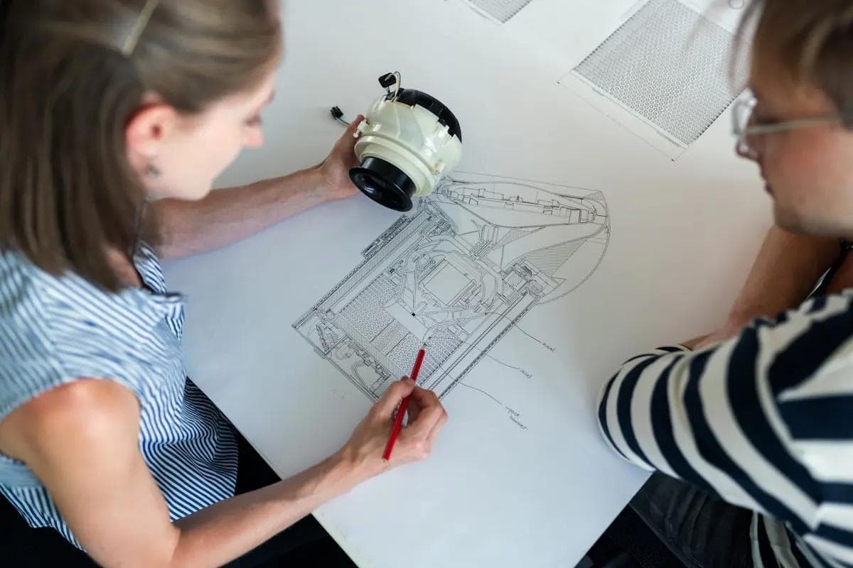
Chemistry, mechanical and dimensional verification, in-house.

Our in-house MetChem laboratory provides spectrometer chemistry analysis, tensile testing and dimensional / metallurgical inspection on the same floor as the casting line. Reports are issued against a robust control plan and made available to customers on request.

  • ChemistryOE spectrometer
  • MechanicalTensile tester
  • DimensionalCMM (planned)
  • SystemIATF 16949
SectionAlloys

Three alloys, chosen for braking duty.

Each alloy is matched to a component's role in the brake system: structural caliper bodies, bore-tolerant cylinders, or weight-optimised brackets. All three are cast in the same plant under the same QMS.

Swipe to compare →

PropertyAC2AHigh strength · structuralLM16Heat-treatable · balancedAl-Si7Castability · thin-section
Primary useCaliper bodiesMaster cylindersCaliper bodiesWheel cylinders · bracketsBracketsComplex thin-wall geometry
Silicon (Si)~5%High-strength matrix~5%Balanced casting~7%Highest fluidity
Copper (Cu)~4%Strength contribution~1.5%ModerateTraceLow
Heat treatmentT6 standardSolution + ageT6 / T4 / customWide windowT6 optionalOften as-cast
Strength characterHigh UTSStructural-gradeBalanced UTS / ductilityWorkhorseModerateGeometry-driven
CastabilityGoodStable in GDCVery goodForgivingExcellentThin sections
Typical platforms2W · 3W · 4W*Safety-critical2W · 3WHigh-volume2W · 3WBracketry

* Four-wheeler caliper programmes in development. Specific chemistry, mechanical properties and acceptance criteria are issued per part on the customer's drawing & control plan.

SectionEngineering

More than a casting house.

We work with customer engineering from the first sketch, feeding back manufacturability, value-engineering opportunities and tooling realities before a die is cut.

DFM

Design for Manufacturability

We review every new geometry against gravity-die-casting realities (wall sections, draft, gating, hotspots) and feed changes back during RFQ, before a die is ordered.

Output: annotated DFM report · proposed revisions
VAVE

Value Analysis / Value Engineering

On running programmes we propose weight, cycle-time and material-cost reductions. The VAVE tandem master cylinder is our anchor case: a multi-feature casting, fully re-engineered.

Output: VAVE proposal · sample · validation plan
TOOL

Tooling via Renuka Engineers

Tools are designed, built and reworked at our sister facility, Renuka Engineers, keeping die ownership and turnaround inside one accountable group.

Output: tool drawings · die · rework cycle
PPAP

Sampling & PPAP

From first-off samples through dimensional layout, capability studies and PPAP submission: the documentation set Tier-1 buyers require before SOP.

Output: PPAP file · CpK data · IMDS
SectionDesign & development

You own the design. We engineer how it's made.

Every programme begins and ends with the customer. You bring the part; we bring its manufacture. Through this loop we take your drawing to validated, sampled castings — while design authority for the product stays with you at every step.

01

Your drawing & 3D model

You provide the 2D drawing and 3D model. The product design — geometry, function and specification — is yours, and stays yours through every stage that follows.

02

Manufacturing feasibility study

We assess castability against your geometry: wall sections, draft, gating and shrinkage, tooling implications and alloy fit, before any commitment is made.

03

Updated 3D model for your approval

Where casting requires it, we recommend manufacturing-feasibility refinements and return the marked-up model. You review and approve every change; design authority remains with you.

04

Die design

We design the gravity die, gating and feeding system to reproduce your part — built and reworked at our sister tool room, Renuka Engineers.

05

Die & process design validation

Tooling and process parameters are validated through first-article trials, confirming the process reproduces your design intent at rate.

06

Inspection & sample submission

Dimensional, metallurgical and chemistry verification in the MetChem lab; first-off samples and the PPAP file submitted for your sign-off.

Manufacturing process and tooling design sit with MAP Alloys; product-design authority remains with the customer — consistent with the scope of our IATF 16949:2016 certification.

SectionHow we work

From RFQ to SOP: the way OEM sourcing actually works.

A typical new programme moves through these seven stages. Lead times below are indicative; firm timelines are quoted against component complexity and tooling scope.

Ready to start a programme?